CarKit
Published on: November 25, 2025
4 min read
CarKit
A Swiss-Army-Knife Control Board for DIY RC Chaos™
(You bring the chassis. It brings the brains.)
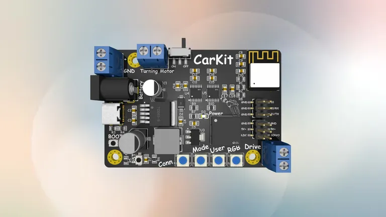
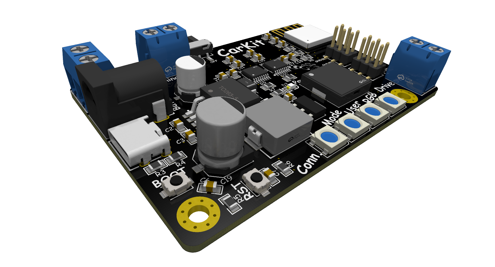
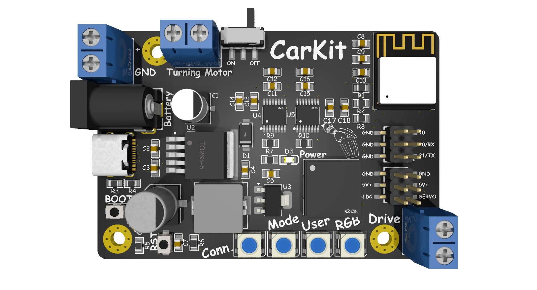
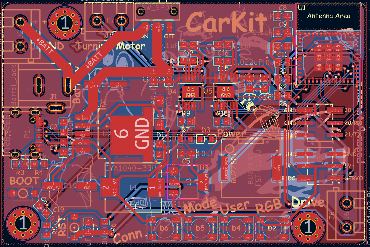
Renders
Visuals because everyone loves eye candy.
What is this?
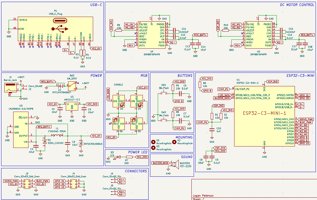
This is a do-it-all RC control board built around an ESP32-C3, designed to handle basically everything you might want on a DIY RC car:
- 2 DC motors with PWM (think: drive + steering/turning)
- 1 BLDC motor output (via external ESC)
- 1 servo motor output
- Bluetooth gamepad support (so you can use almost any Bluetooth controller)
- Multiple power input options (USB-C, barrel jack, or raw battery via screw terminals)
- 4 RGB status LEDs for connection, mode, and “because RGB”
- On-board buzzer for beeps, alerts, and dramatic startup tones
It’s meant to be the drop-in brain for “I duct-taped this together but now I want it to drive nicely” RC builds.
BOM
All the silicon, blinkenlights, and screw-down bits live here.
Features
Motor Control
- 2× DC motor channels
- PWM control for speed
- Direction control via DRV8876
- Great for drive + steering or tank drive* setups
- 1× BLDC channel (signal)
- Standard PWM output to an external ESC
- 1× Servo output
- For steering, camera gimbals, or cursed animatronics
Power Options
Because every DIY RC build uses a different battery, obviously.
- USB-C (5 V)
- For bench testing, firmware dev, and flexing modern ports
- Barrel jack
- Perfect for 9 V batteries or standard DC wall adapters
- Screw terminals
- Bring your own LiPo / battery pack
(Dont feed the board anything over 36V, I would recommend staying under 24V)
LEDs & Buttons
- 4× SK6812 RGB LEDs
- Can show:
- Connection status (paired / searching / sad)
- Board mode (e.g. normal, config, debug)
- User-defined patterns (rainbow, brake lights, underglow, whatever)
- Can show:
- 1× Power LED
- Because sometimes you just need “is this thing on?”
- Tactile buttons
- For reset and boot functions (programming)
Connectivity & IO
- ESP32-C3 MCU
- Wi-Fi + Bluetooth LE
- Extra GPIOs broken out via 2×3 SMT headers for expansion
- Screw terminal outputs
- For motors and power
Motor Channels Overview
| Channel | Type | Typical Use | Notes |
|---|---|---|---|
| M1 | DC Motor | Main Drive | PWM + DIR via DRV8876 |
| M2 | DC Motor | Turning / Steering | PWM + DIR via DRV8876 |
| BLDC OUT | PWM Signal | Brushless ESC Input | External ESC drives the BLDC motor |
| SERVO OUT | Servo PWM | Steering / Gimbal / Etc. | Standard RC-style servo signal |
How It Works
At a high level:
- You power the board via USB-C, barrel jack, or screw terminals.
- The LM2596 generates a solid 5 V rail, and the AMS1117 creates the 3.3 V rail for the ESP32-C3.
- The ESP32-C3 runs your firmware:
- Reads input from a Bluetooth controller
- Outputs PWM and direction signals to the DRV8876 for the DC motors
- Generates PWM for the BLDC ESC and servo
- Drives the SK6812 RGB LEDs and buzzer to show status and vibes
All the “annoying parts” (power, drivers, IO protection, connectors, etc.) are on the PCB, so you can focus on mechanical design.
Using a Bluetooth Controller
The exact firmware and controller mapping is up to you and some basic stuff is included, but the general idea is:
- Flash your ESP32-C3 firmware that:
- Pairs with a Bluetooth gamepad / controller
- Maps sticks/triggers/buttons to motor speeds and steering
- On startup, the RGB LEDs can:
- Pulse / chase while waiting for a controller
- Turn solid once connected
- Drive your RC car like a normal RC car, but with way more flexibility and hackability.
(You can map “A” to beep the buzzer. You absolutely should.)
RGB LEDs
Because a control board without RGB is just morally wrong.
Possible roles for the 4 SK6812 LEDs:
- LED 1 – Connection status (Bluetooth)
- LED 2 – Mode indicator (normal / config / debug)
- LED 3-4 – User bling (animations, underglow, warnings, etc.)
Or ignore all that and just run full rainbow vomit. No judgment.
Why?
This board exists for that moment when you’ve got:
- An RC chassis
- Some motors
- A pile of batteries
- And zero desire to reinvent “basic motor control + power + Bluetooth” again
It’s meant to be the one board that handles:
- Motors
- Power
- Input
- Feedback
…so you can just design something cool and let this handle the boring electronics.
Project State
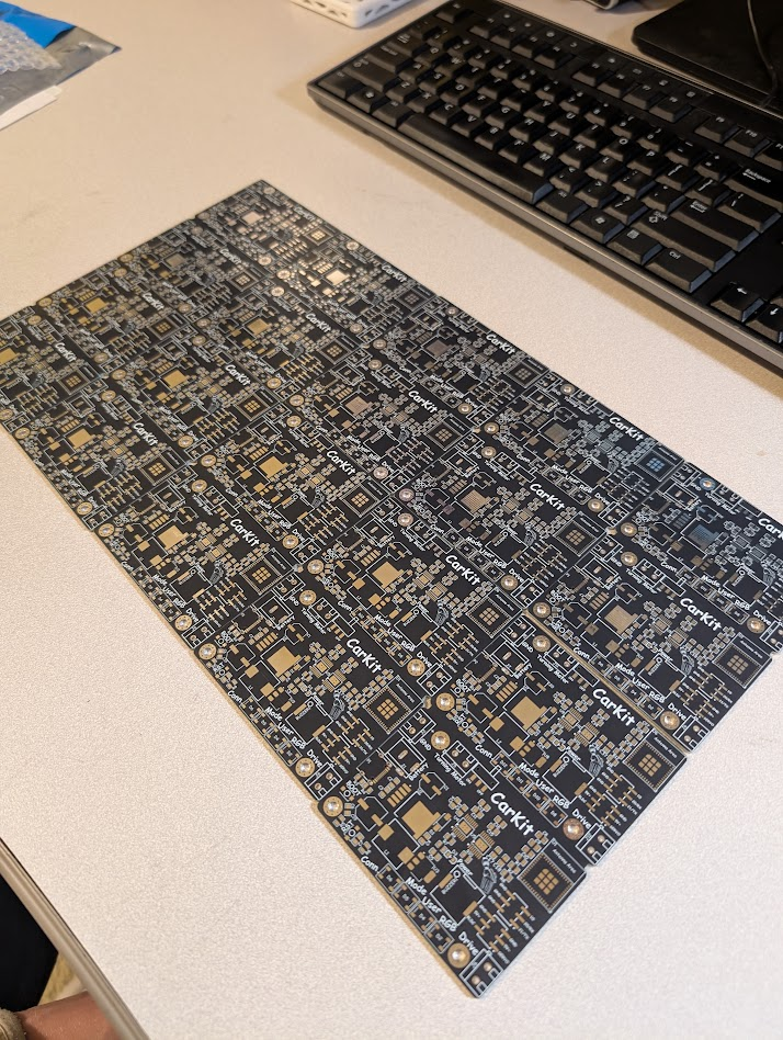
I have all of the parts to assemble the PCBs, and I plan to do so soon.
I ordered the PCBs as a panel to reduce cost, however they were not cut apart when they arrived. Once I cut them apart I will be able to assemble them.
Disclaimer
This project is open-source, powered by vibes, and tested mostly on my own questionable hardware.
If you:
- Overvolt it
- Reverse the battery
- Strap it to a rocket
- Or send 48 V into something that wanted 5 V
…and it smokes, explodes, or develops sentience, that’s entirely on you.
Happy hacking!