Fracture
Published on: December 31, 2025
10 min read

Fracture
A modular, glowing wall of keys with its own brain, synth, and buzzer per board.
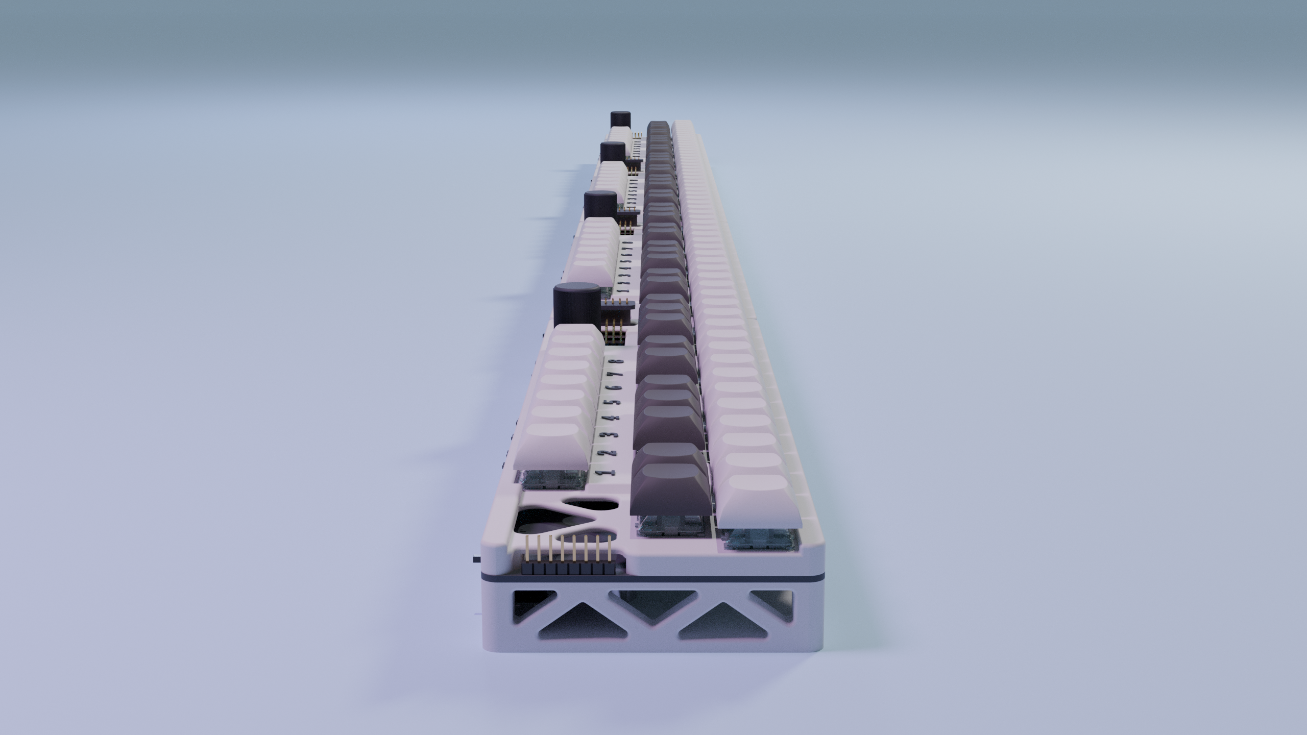
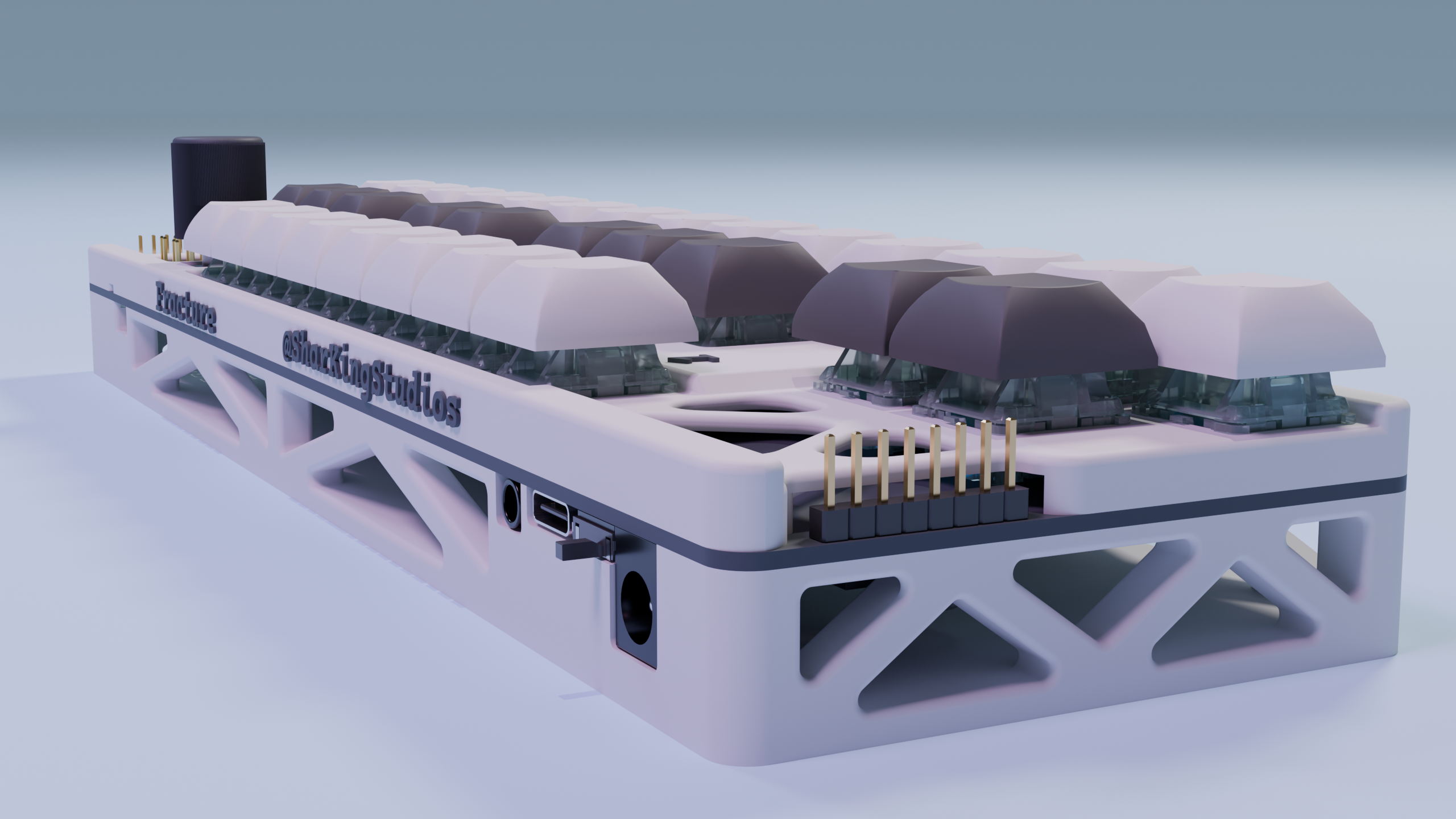
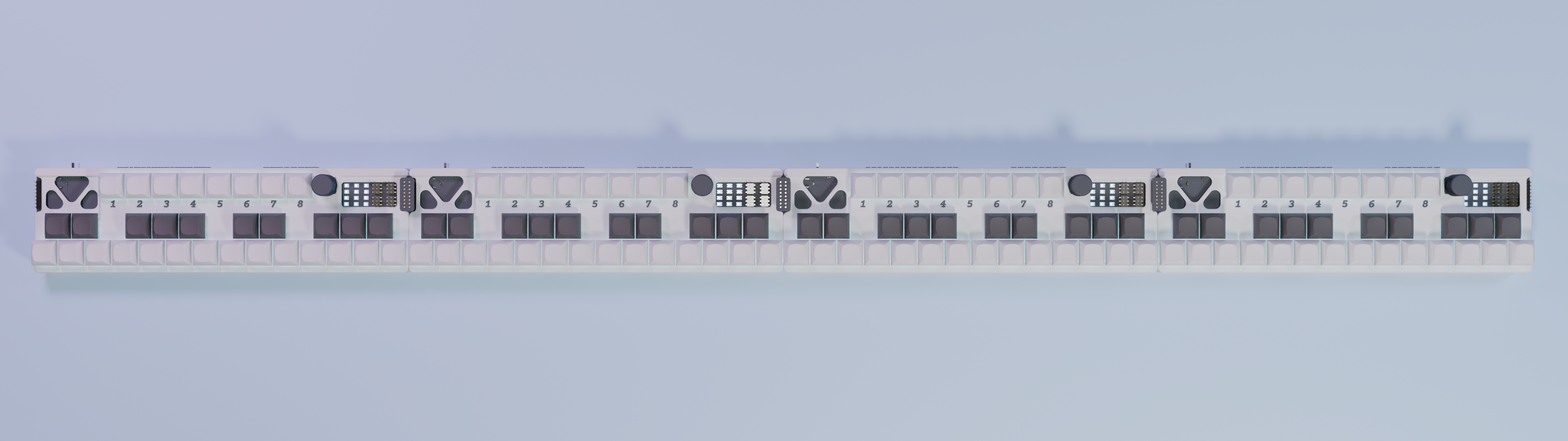
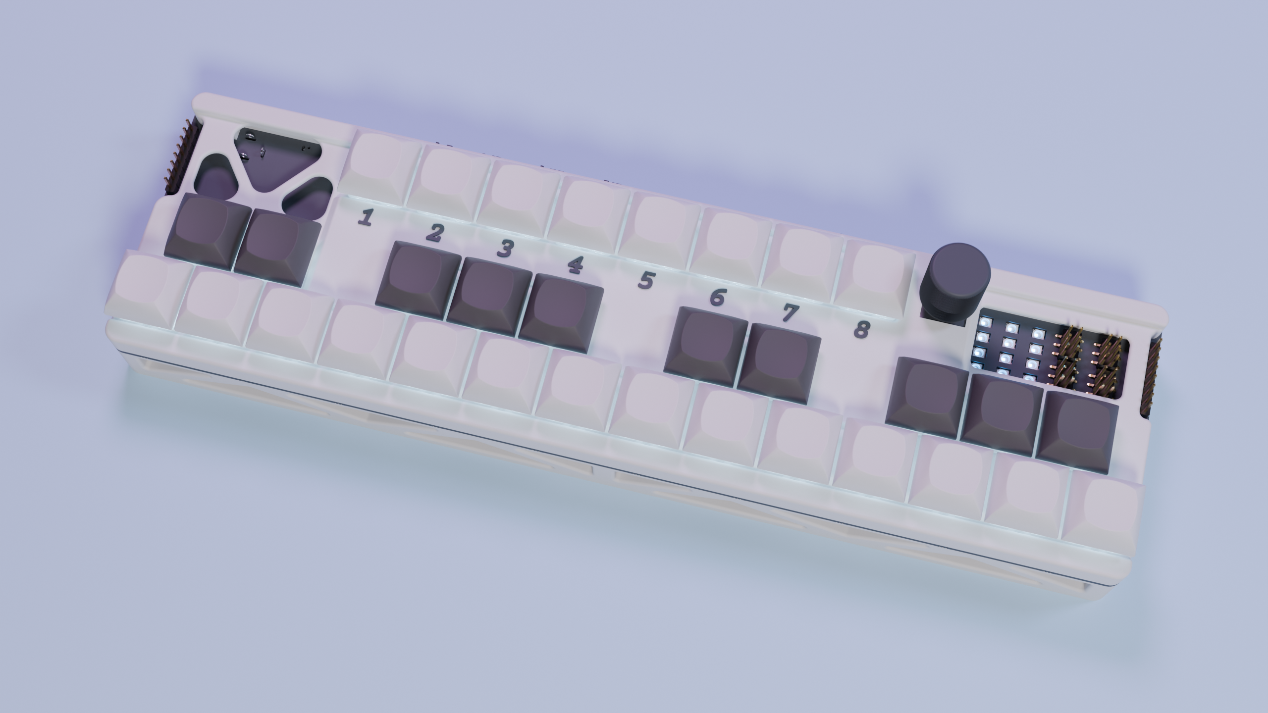
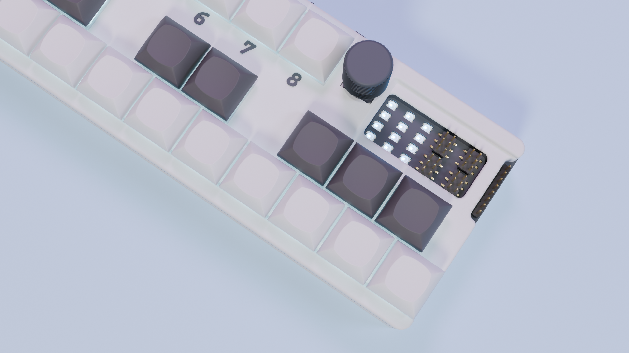
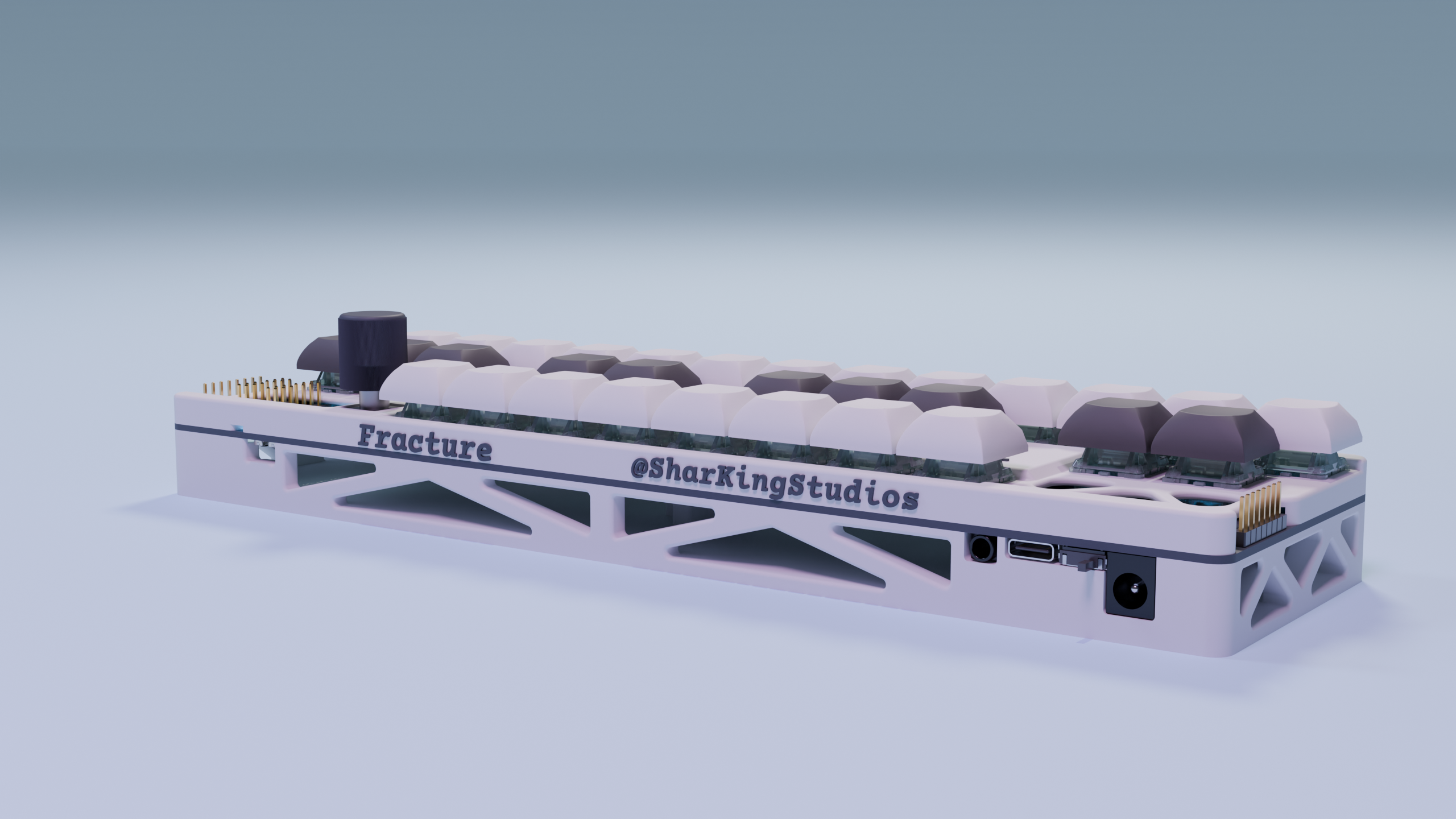
Renders
Visuals because everyone loves eye candy.


What is this?
It’s an infinitely expandable MIDI keyboard system built around an ESP32-S3, designed so each board is a fully-featured synth module. When you connect a bunch together, they behave like one giant, continuous instrument. Each board gives you 2 octaves of hall-effect keys (24 main keys), plus 8 “function” keys for extra tricks. It also has onboard I2S audio output, a buzzer synth per board, and 45 addressable RGB LEDs for underglow + status. Boards talk to each other over RS-485 chaining so note events get shared, and it also does USB MIDI, meaning any board plugged into your computer speaks for the whole keyboard.
One board is fun.
Four boards gives you a full velocity sensing piano.
Features
Infinitely Chainable Boards
Each board is its own little 2-octave chunk: 24 main keys and 8 extra keys for function/mode stuff. The boards discover each other physically using an RS-485 bus (SP3485) and left/right neighbor sense pins, so you can keep chaining them together.
Hall-Effect Velocity Sensing
No mushy rubber domes here. Keys are read using dual 74HC4067 analog multiplexers, and velocity is computed using the time between “start of motion” and “fully pressed”.
It’s all done in firmware - no external velocity hardware, just some math and a lot of analog readings.
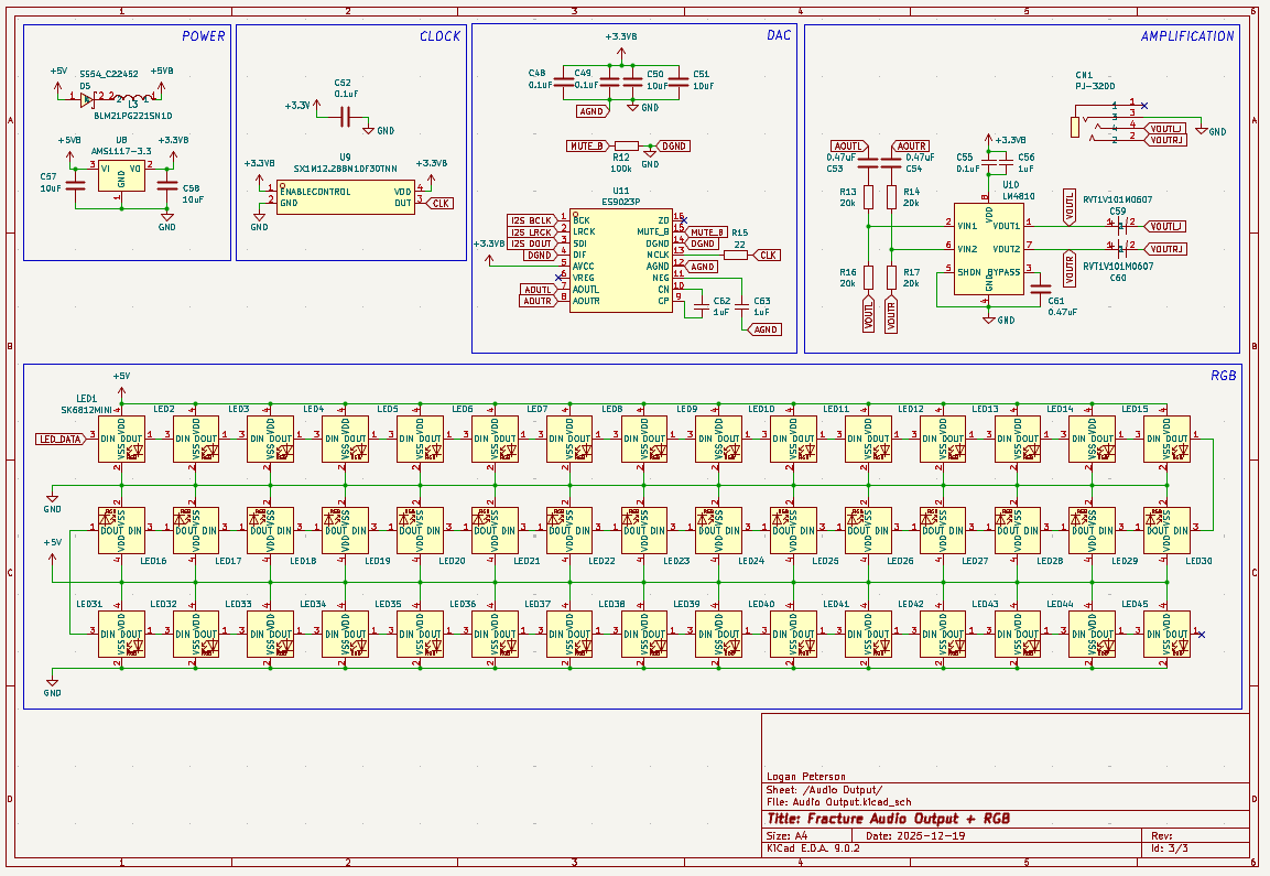
Onboard Polyphonic Synth (I2S DAC)
Each board is a tiny synth. It uses an ES9023P I2S DAC driven at 44.1 kHz, stereo, and supports up to 8 simultaneous voices.
You don’t need a computer to hear anything, the keyboard can sing on its own.
Polyphonic Buzzer Per Board
Because one audio path wasn’t enough. Each board also has a timer-driven buzzer synth that runs at a 20 kHz sample rate. It’s used for a startup jingle, any feedback sounds, and mild harassment of anyone nearby.
RGB Overlay (Key Underglow + Debug UI)
Each board has 45 WS2812 LEDs and they’re not just there to look pretty (but they do). Every note triggers a “splash in the pond” ripple, and the ripple spreads based on MIDI note distances, not physical LED position. Since note events are shared over RS-485, the ripple effect works across all boards.
Basically: the keyboard tells you how it feels in RGB.
USB MIDI for the Entire Chain
Any board plugged into USB exposes MIDI for all boards. So you can plug in literally any board in the chain, open your DAW / synth, and play the entire keyboard from that one cable.
Rotary Encoder
Because knobs are scientifically proven to make things better.
BOM
All the silicon, magnetics, and glowsticks live here.
Why?
Because regular MIDI controllers are boring. Off-the-shelf keyboards don’t re-map themselves and you usually cant chain them together.
Fracture exists to be modular, mildly smart, and just slightly over-engineered.
I honestly thought this would be an easier project, but feature creep got the best of me…
Development Log
12/23/2025 8:46 PM - Created the Specifications
I started this project by outlining all of the goals I have for what specifically I want this thing to do.
The hardest thing about this stage was figuring out how I was going to do per key velocity sensing. I ended up going with the idea of using analog hall effect keyswitches. I don’t think they will be as good as a normal keyboard, but it should be worlds better than just a normal keyswitch.
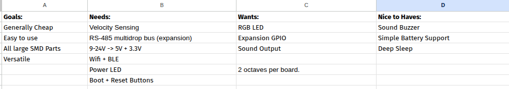
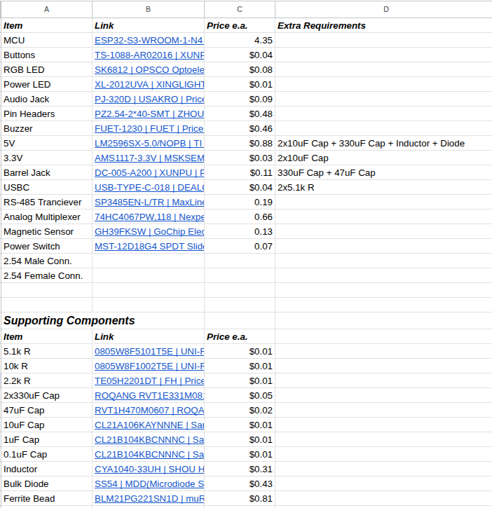
I also put together a list of some components I would need to create this design:
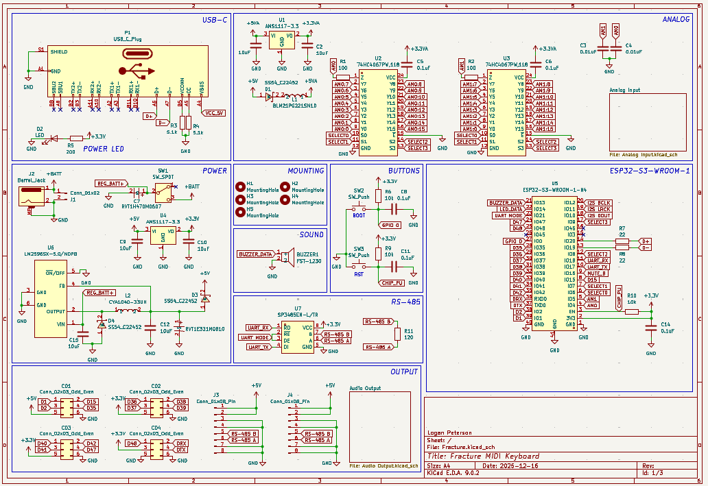
12/23/2025 8:52 PM - Finished the Schematic
All these analog components are making the schematic pretty interesting. I had to make sure the signals were well isolated so I gave them their own 3.3V supply.
I got all the components imported and used their datasheets to connect everything together. It ended up taking the entire day, but everything should be done on the schematic side at this point.
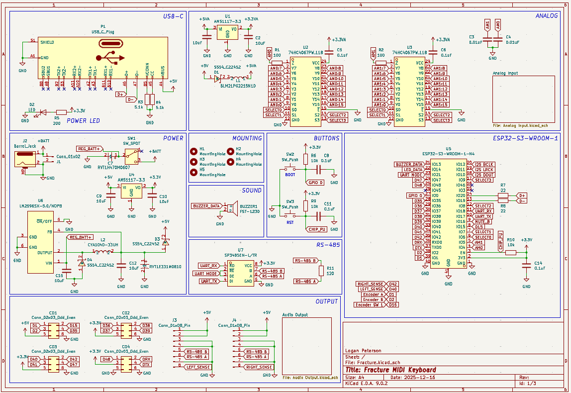
It ended up being so big it had to be split into 3 different sheets:
Heres the main one:
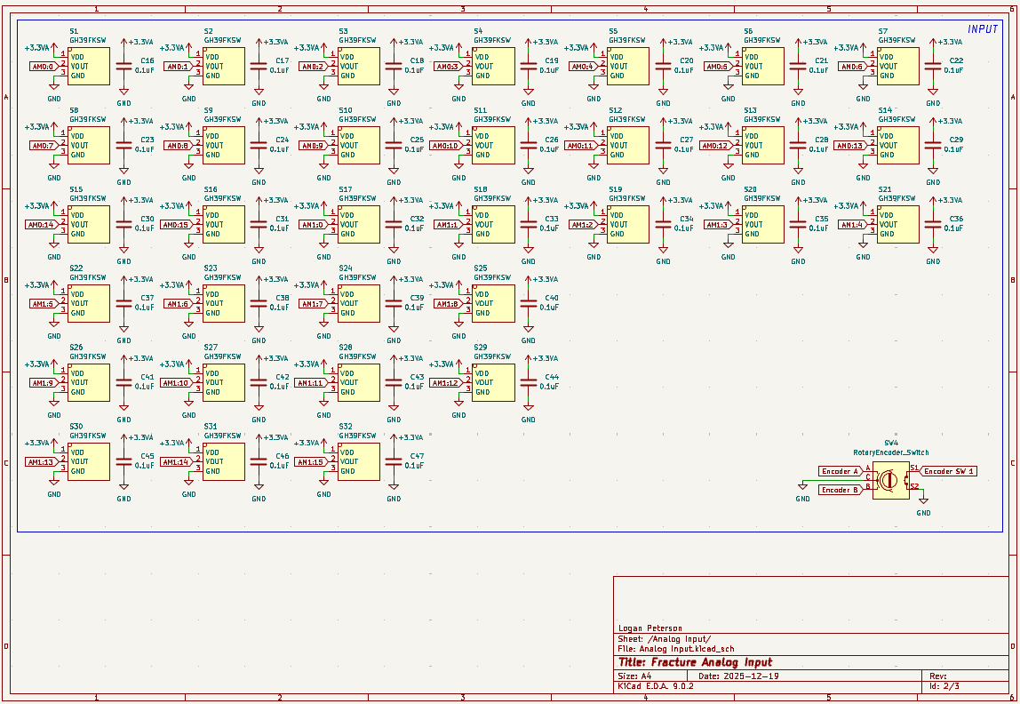
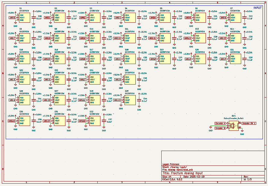
Heres the input page:
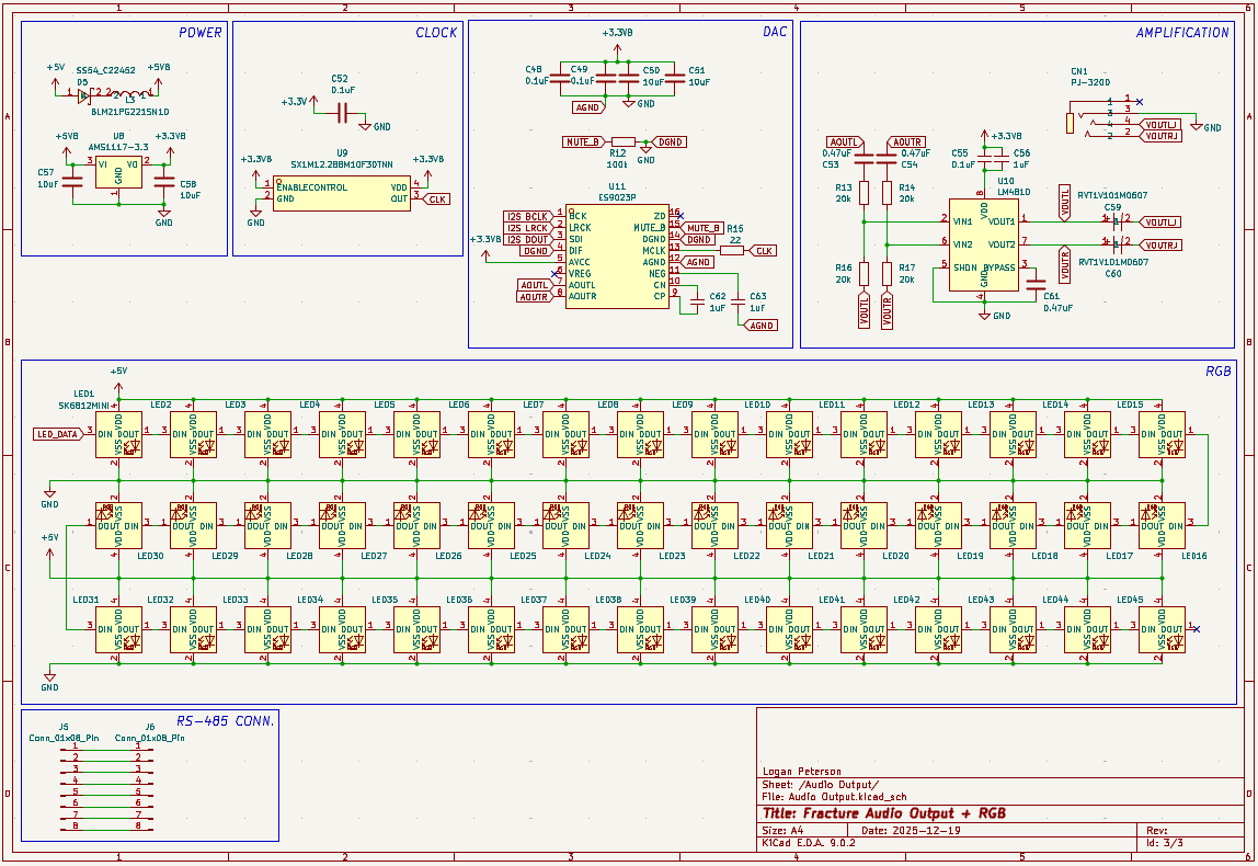
And heres the output page:
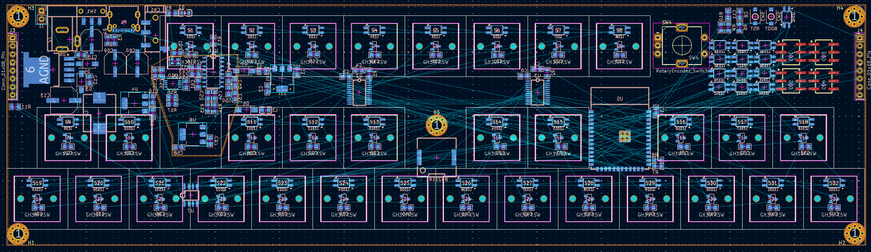
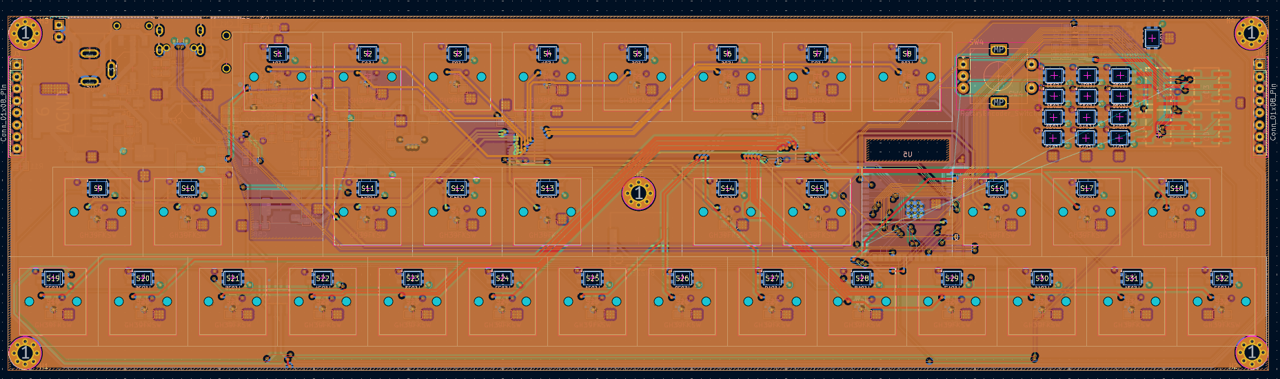
12/23/2025 8:57 PM - Finished the Layout
I finished combining the keyboard switch footprint with my analog sensor footprint to create the correct holes for the hall effect keyswitch (Since the only analog keyswitch footprint I could find were Void Switches).
I also finished putting all of the components from my schematic into my PCB. I wanted to keep it as thin as reasonably possible, while keeping the function keys away from the second row so I don’t accidentally press it while playing.
Anyway here’s what the PCB looks like now:
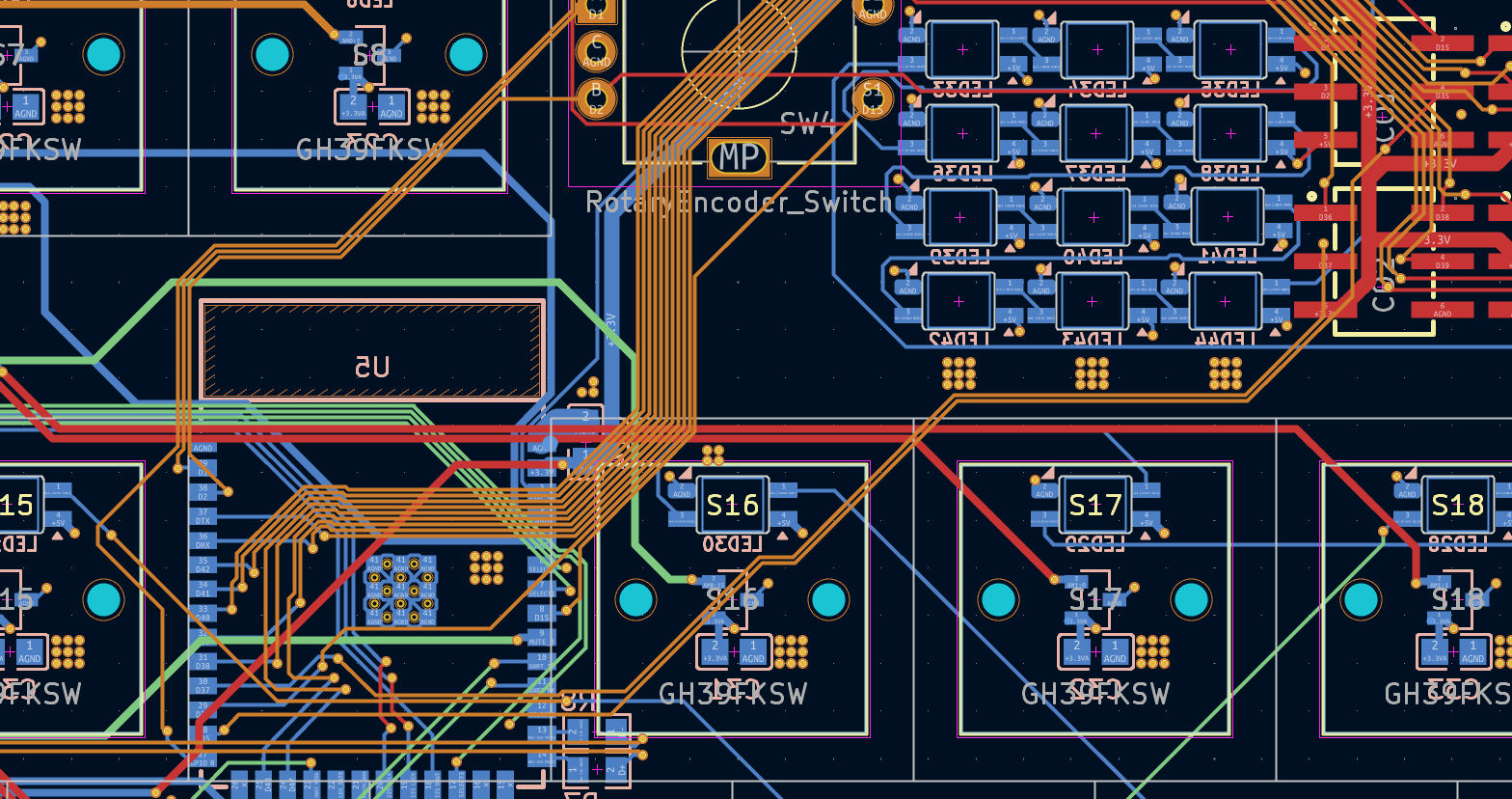
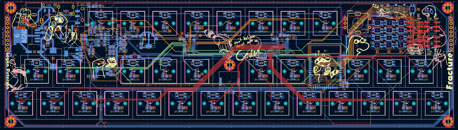
12/23/2025 9:02 PM - Finished Routing the PCB
I finished routing all of the PCB. This is my first PCB that I designed with 4 layers initially in mind. It does make it quite a bit easier, so I used the extra space to make all of the traces nice and pretty. Look at all those massive data lines…
Anyway heres what the PCB looks like now:

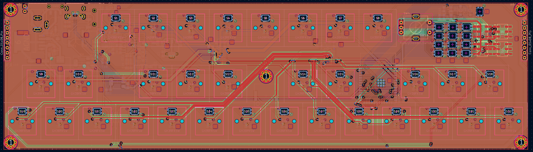
And it even has no DRC Errors!

12/23/2025 9:05 PM - Fixing a silly little mistake
Oopsies…
I forgot that the footprint I imported for my ESP32 didnt include a keepout zone for the antenna, and I had routed a ton of traces right over it…
Well after shifting things around a bit and adding a keepout for all the zone fills I got this:
12/23/2025 9:13 PM - Panelization (The better way)
The last time I tried to panelize stuff the PCB manufacturer didn’t actually do the VCUTs (Because I didnt pay extra for them to treat it like a panel..). This time I am going to do mouse bites. It took a bit of tweaking to get these to work. It was mainly an issue with the PCB Editor snap size and all the footprints not lining up but I got it to work in the end.
While I didnt need to panelize the larger PCBs to each other I did want to add some connector PCBs, so this was a good way of doing that.
Heres what the epic PCBs look like now:
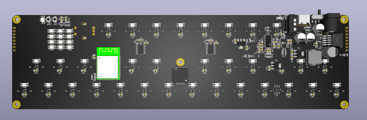
12/23/2025 9:17 PM - Fixed ESP32 Color
The model for the ESP32 that I had found had a bright green PCB color, which didnt match the product or my design at all, so I wanted to change it.
I imported the file into Onshape and selected every single side that was green and changed it over to black. I also removed the LCSC logo :p
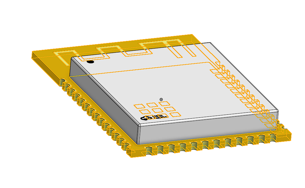
After I fixed the color I exported that and brought it back into my KiCAD project.
Heres what the PCB looks like now:
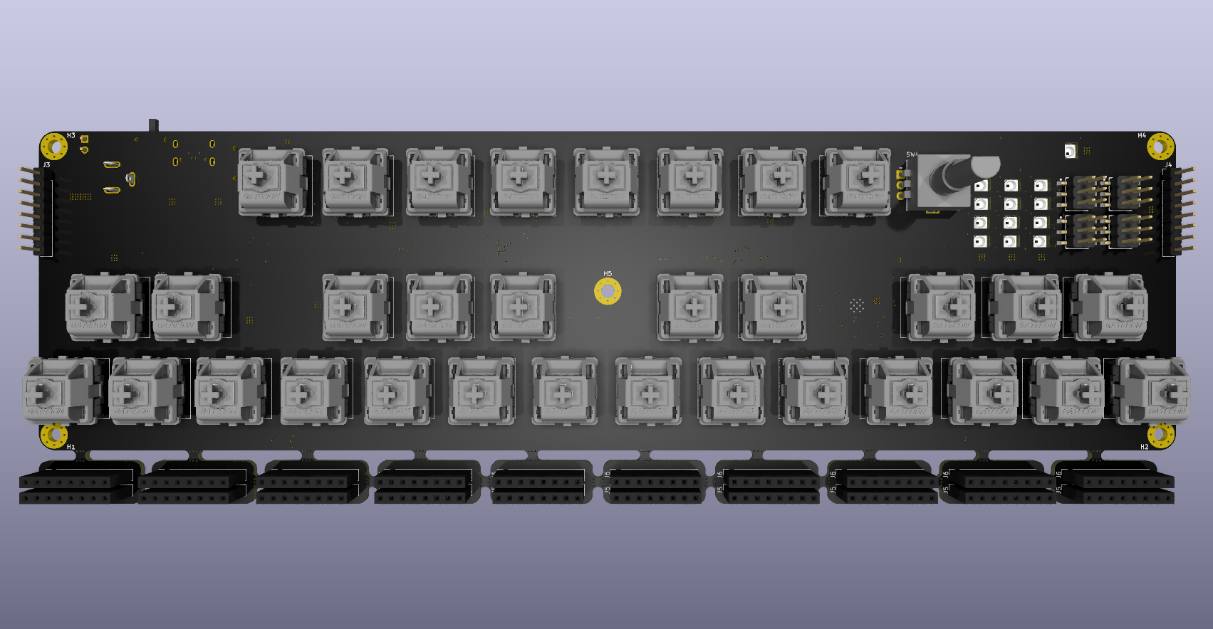
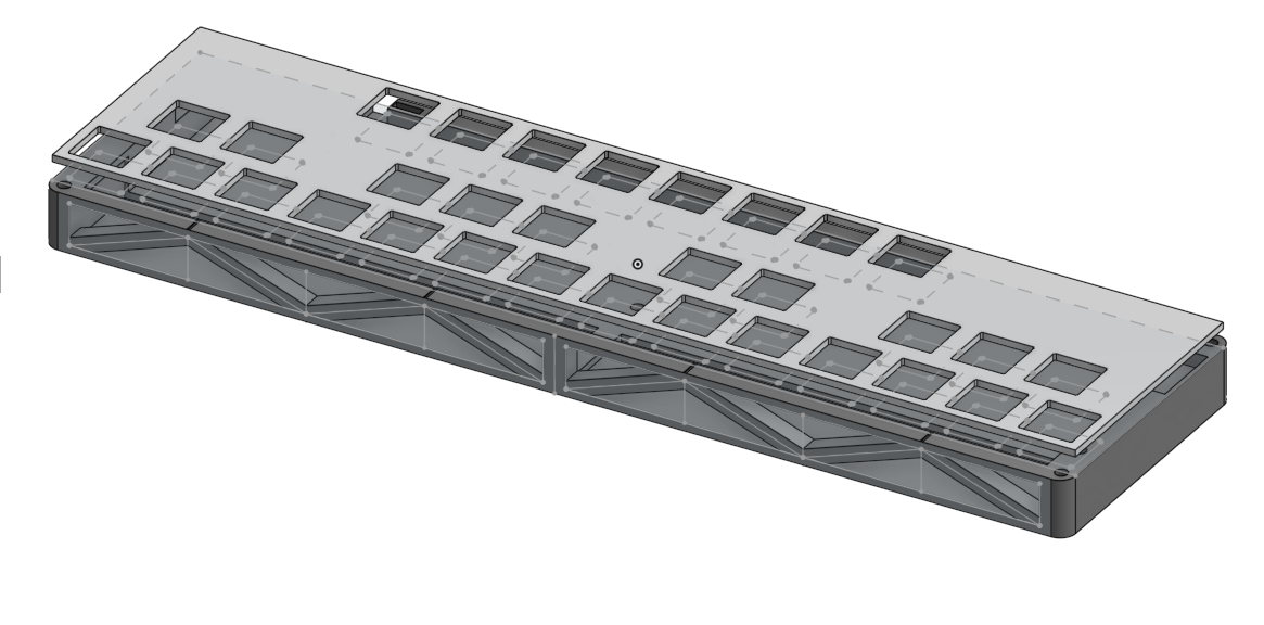
12/23/2025 9:33 PM - CADCADCAD
Banner:

All of the CAD for the project is done at this point.
I started by importing the PCB step file into Onshape and aligning the connector PCBs into their places. Once I finished that I put a keyboard keycap on each switch (manually using mate connectors since I forgot to do this in KiCAD)
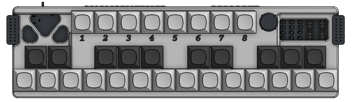
Heres what the CAD Process looked like:
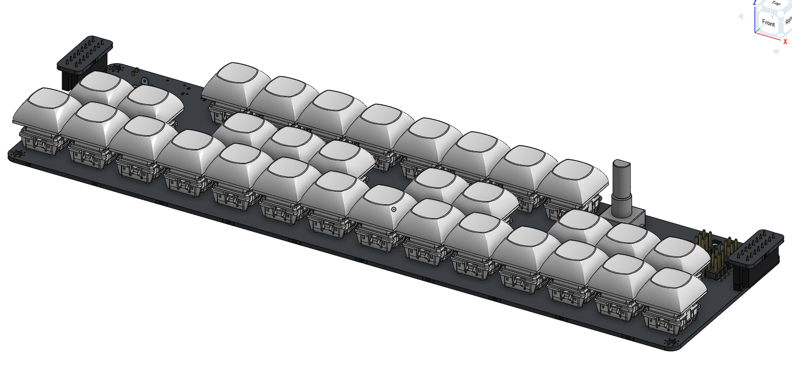
After getting the case files done I imported them into the assembly with the PCBs. It really does look awesome..
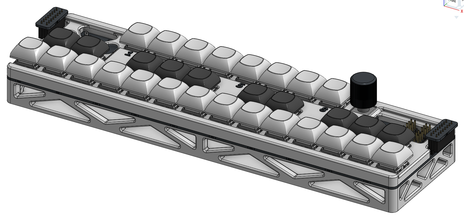
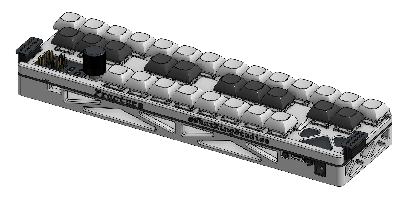
After finishing this assembly I then made the assembly of the entire piano (Made up of the combined 4 sections)
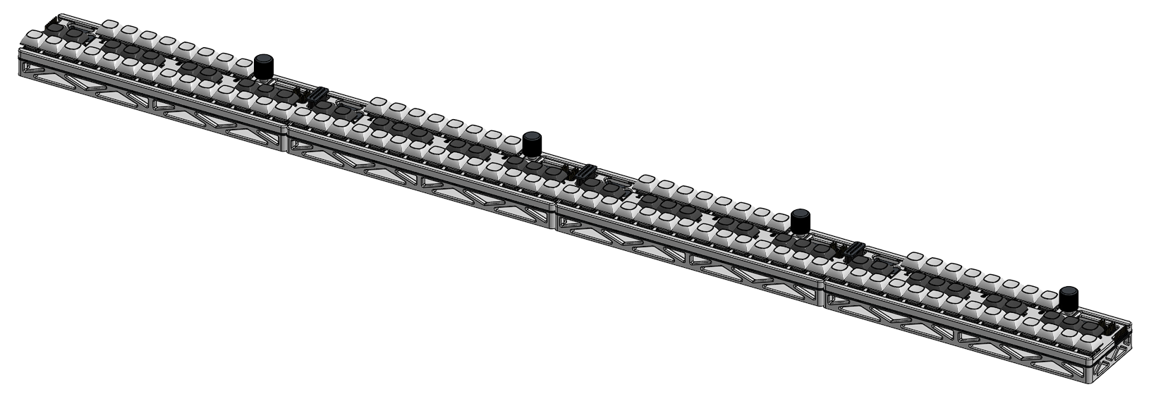
12/26/2025 - Blender Renders
Banner:
Ok this wouldnt have taken so long except that my normal workflow was interrupted…
If I wanted to get this project out with the renders I needed to finish them before I got back home, to my computer with a GPU. This meant that all of my renders were done on a poor laptop with 8GB of ram. (Blender only crashed a couple times…)
I didn’t count the time for when the renders were actually going, since I got up and left but I did count everything else.
My first challenge was getting my Onshape model into something that Blender can actually use. Since it cant normally import a step file and I wasnt about to mess around with Blender Addons I needed to find something that could change my step file over to a GLB file or OBJ file.
My first attempts were downloading freecad and attempting to export the imported step file as a OBJ file, but when I did this I just got the entire thing as a single mesh, which would make it impossible for me to apply different materials to all of the separate objects. (I am sure there is a way to do this in blender but I wouldnt know)
After figuring this out I searched for the solution I used during my last render. It was some random thing called “Cad Assistant” and after I got it working on my linux desktop I was able to finally export the model as a GLB file which I could import into blender.
Once in blender, I created an infinite background and set up lighting and materials.
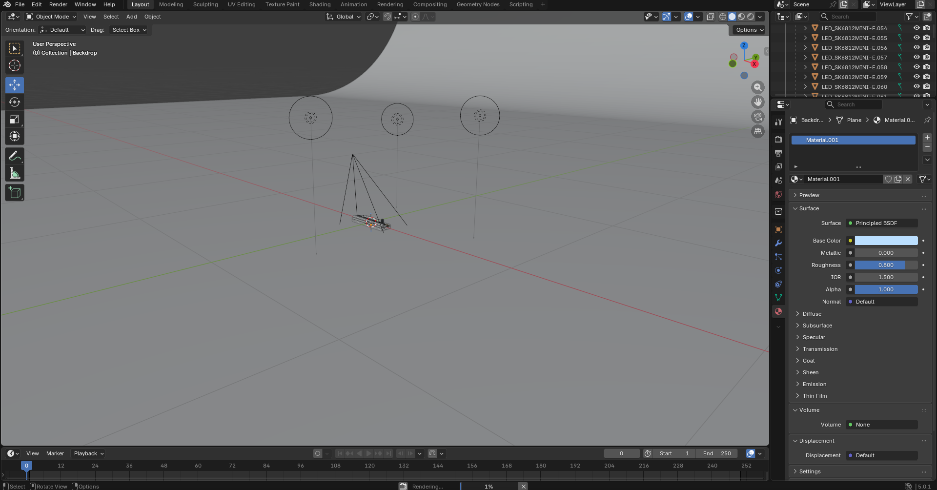
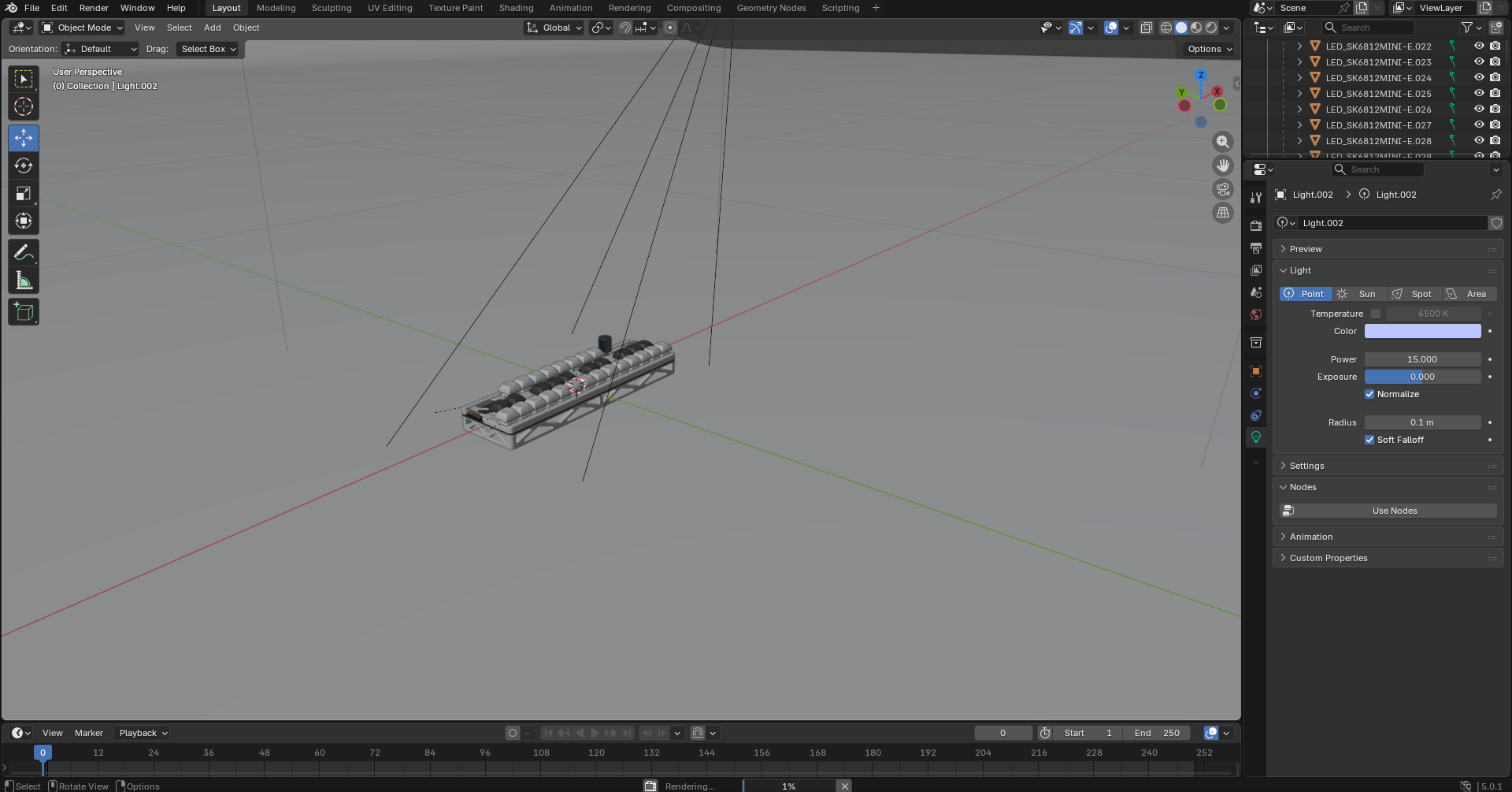
After all that work (And a lot of waiting on the computer which I didn’t include in the time) I got these absolute beauties:


These last 2 renders would crash blender as it finalized the images, meaning I had to both reduce their render times and catch it right before it finished.
12/28/2025 - Finished Firmware
Vibecoding for the win! It still took me a while to define all of the pin mappings and say exactly what I needed everything to do (Theres a ton of stuff on this board)
I’ll show off all of the stuff I added in this firmware in the demo video, but until then you need to read the code to figure it out :shh:
The boards can expand infinitely and automatically remap their positions to play in the correct octaves. All of the MIDI keys also have velocity sensing which propagate to all of the other boards, meaning any of them can be a MIDI output.
Heres a screenshot of some of the constants that can be edited:
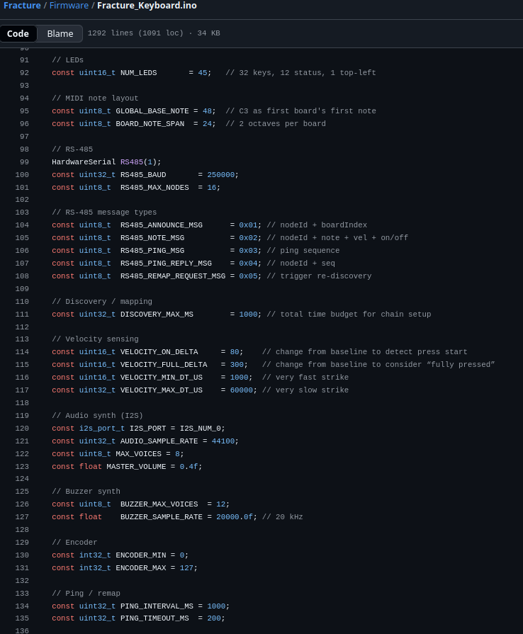
(Wow thats a whole zach latta constants)
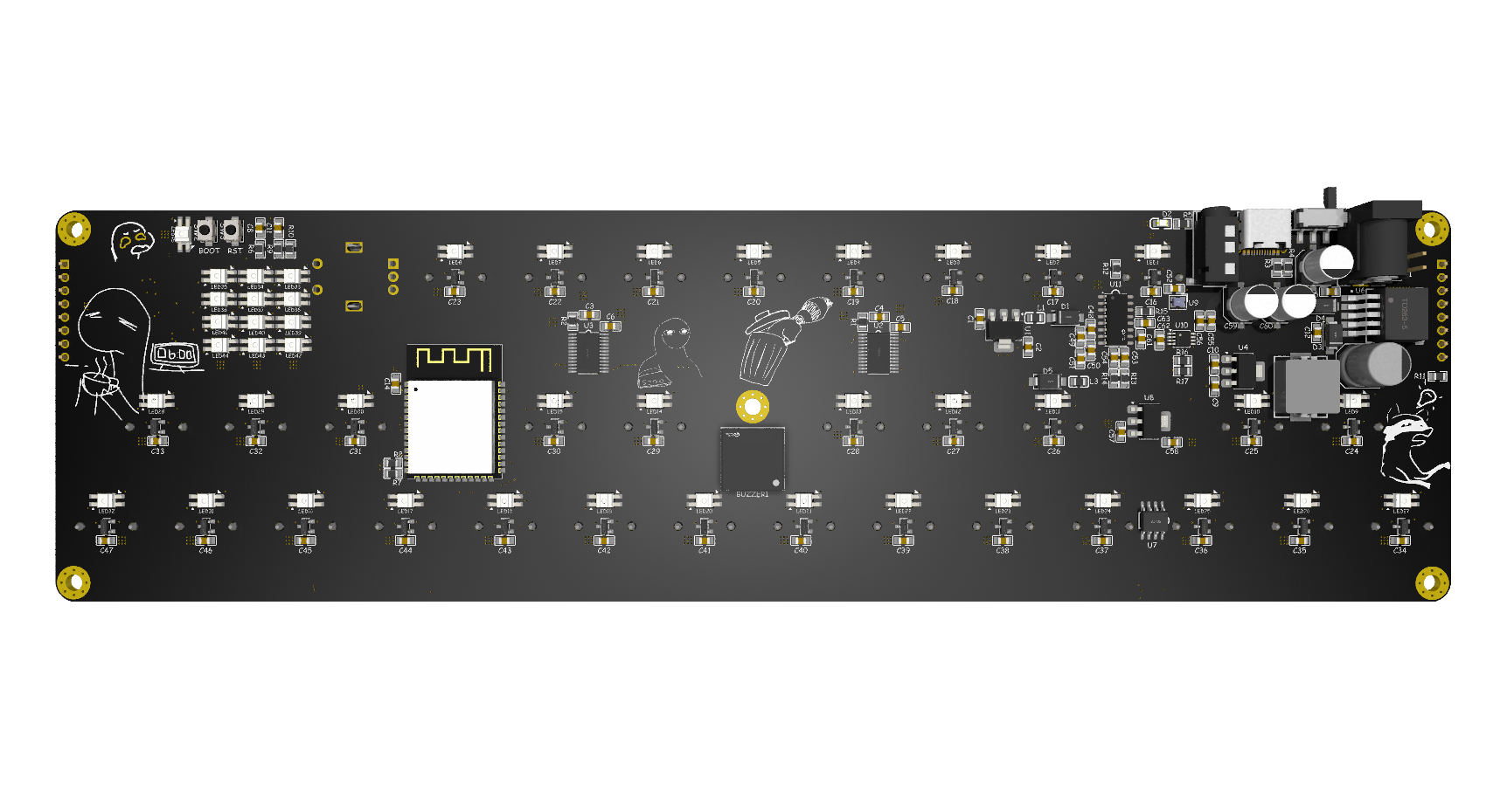
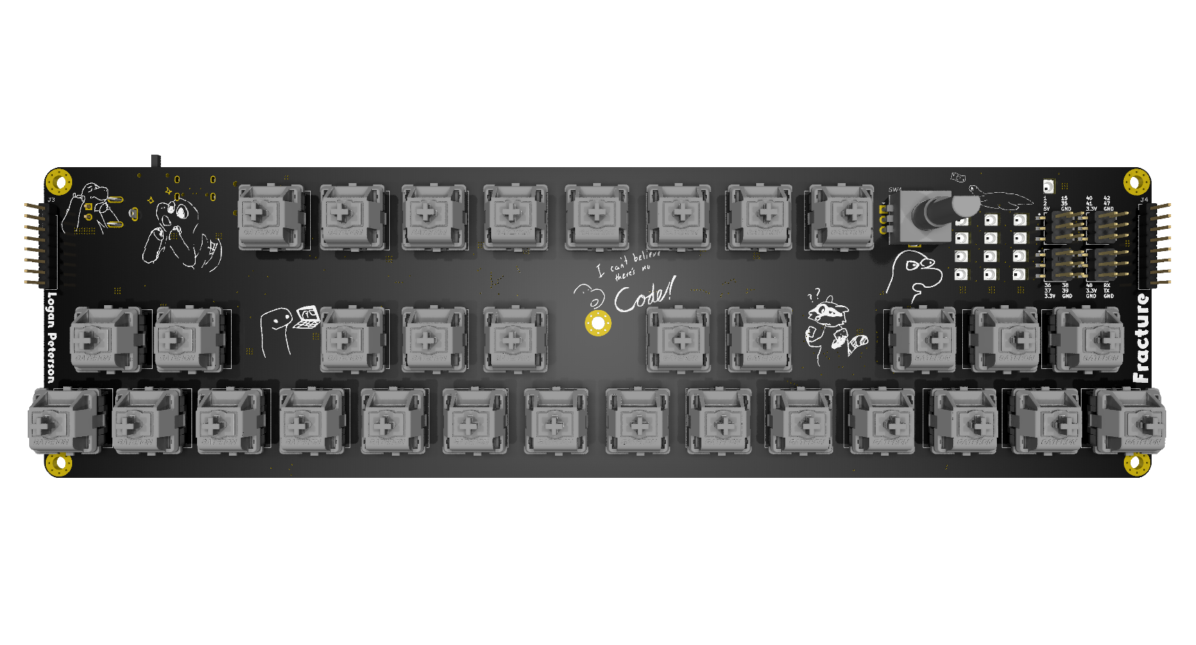
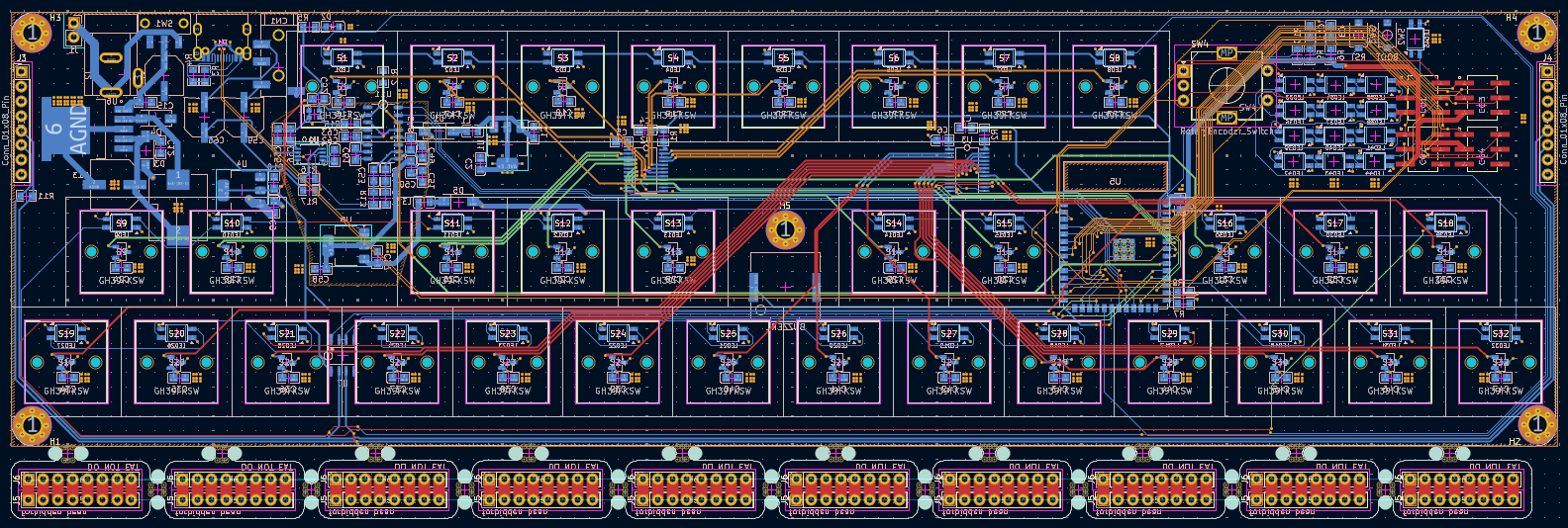
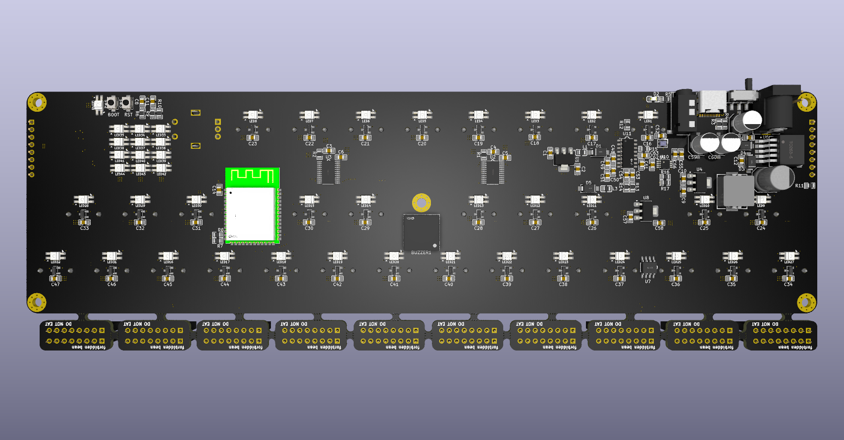
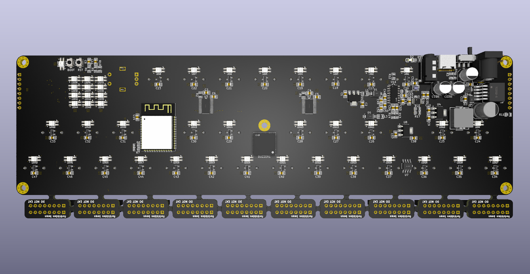
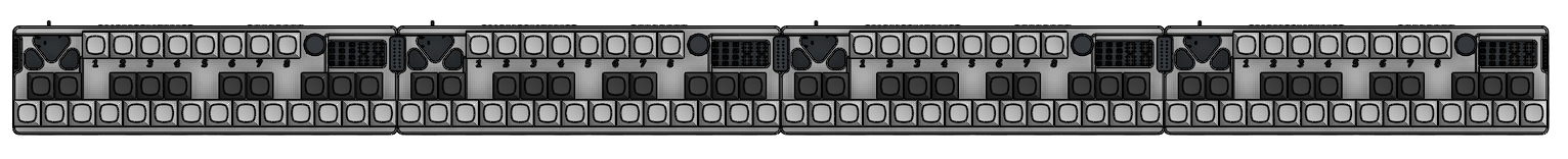
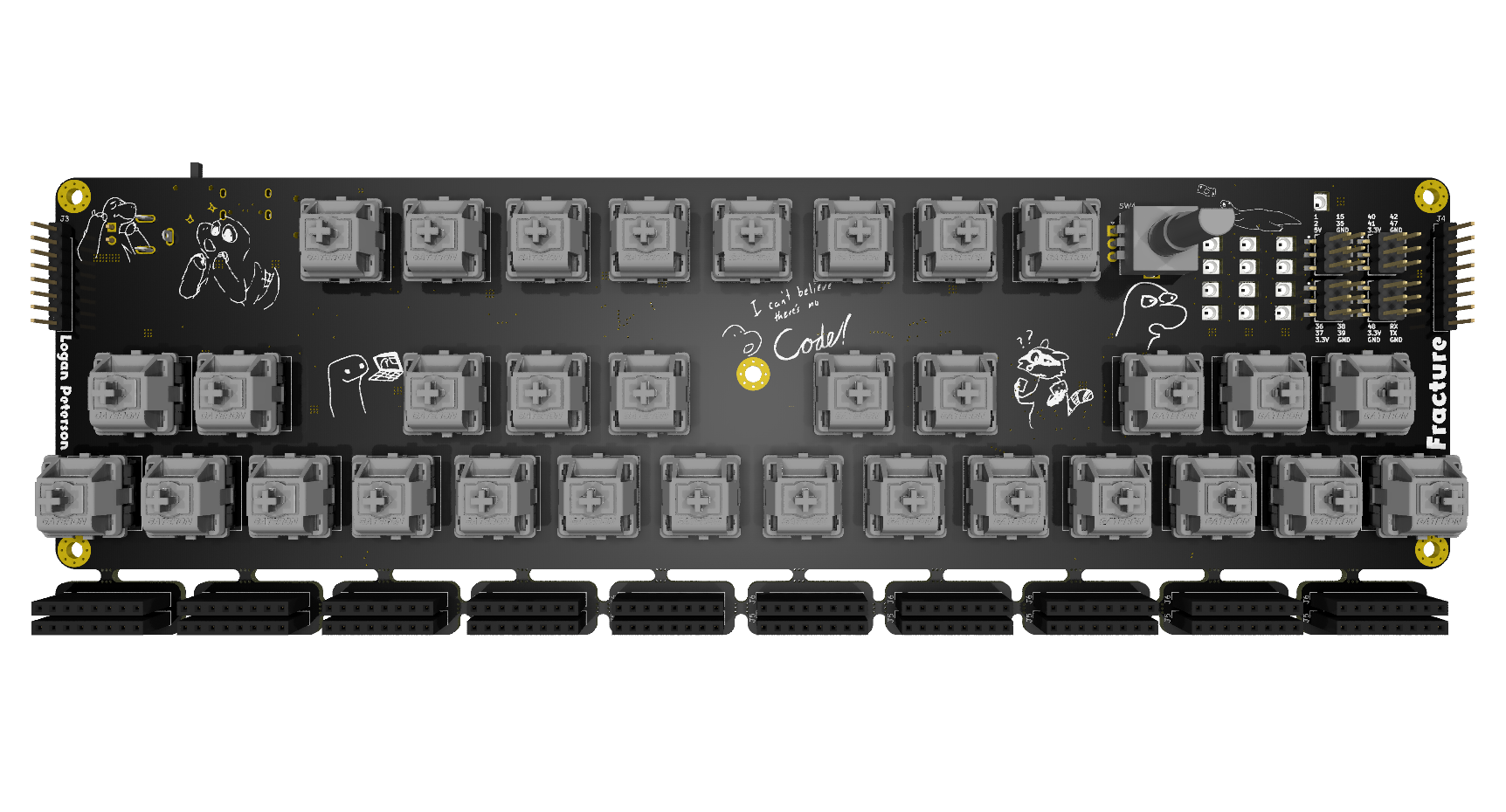
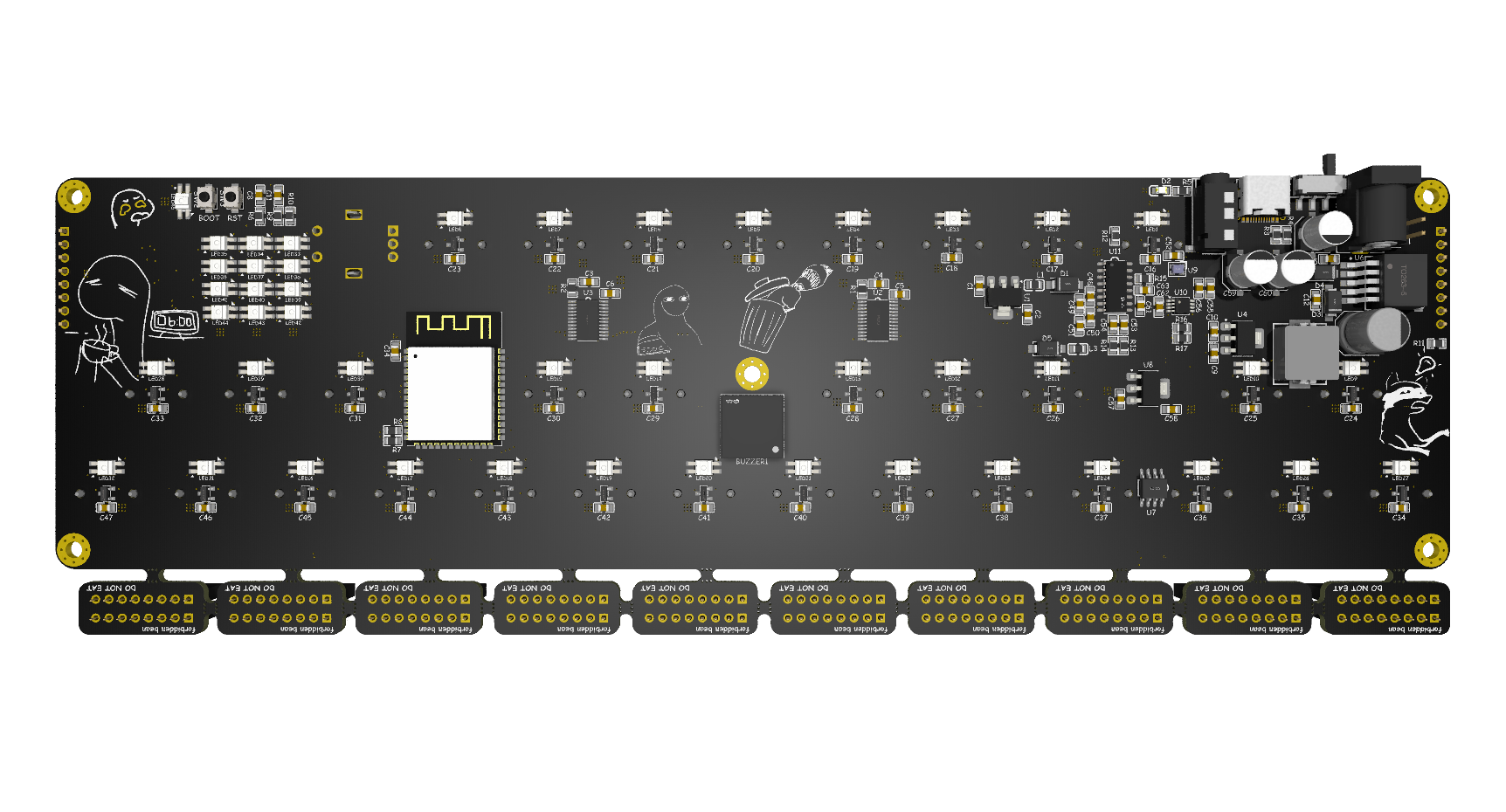
12/30/2025 - Added PCB art and cleaned up silkscreen + PCB Renders
I didn’t think this would take me 2 hours but here we are…
I went through every single item of text and make it comic sans. I also added some silkscreening for my name and the project title, as well as of a bunch of silkscreen art covering the front and back sides of the pcb.
Since the PCBs are finished at this point I also did the renders:
1/1/2026 - BOM and PCB Fab Prep
I finished putting together the bill of materials for the project, it took me a while to find some reasonably priced hall effect key switches.
I get that component count on LCSC isn’t a perfect scale for project complexity, but it seems pretty close :p
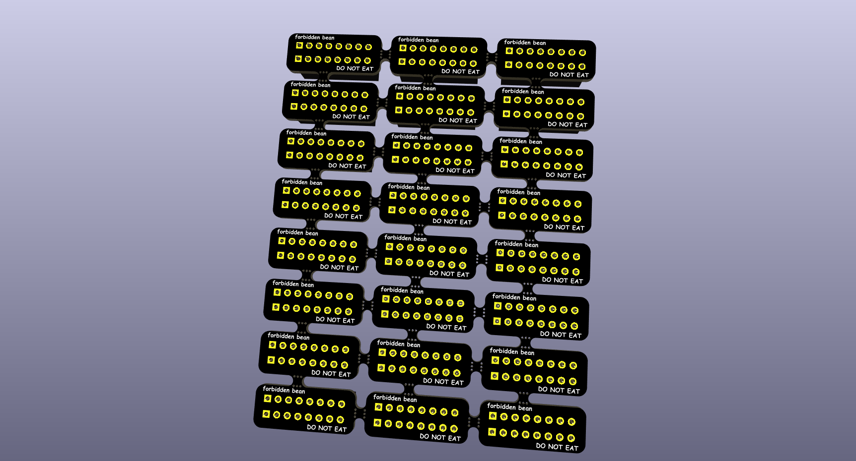
Most of what took so long about this process was going through the JLCPCB Fabrication requirements and docs. After I uploaded the existing Gerbers I got quite the shock after an additional 16 dollar charge was placed on my board for the combination of the connector PCB and main PCB.
As it turns out its way cheaper to make the connector PCB as a separate panel. I also realized I can actually panelize them for no extra cost since they are the same design as each other.
Here’s what that new panel looks like:
Here’s what the main PCB looks like:
The main thing was I added 2 sensing pins to allow the boards to automatically figure out where they are in the list. I also moved a couple traces around for better tolerances. (This part was kinda negligible though)
Disclaimer
This project is open-source and powered by vibes and a sprinkle of C++.
If you:
- Somehow mess up the RS-485 bus
- Drive speakers directly off something that shouldn’t
- Misconfigure power and let the smoke out
That’s on you.