Prism CNC
Published on: March 25, 2026
5 min read
Prism CNC
A compact enclosed desktop PCB milling machine
Renders
Because if the CAD looks good enough, it becomes at least 30% more real.
Project Files
All the CAD, renders, and other files live here.
What is this?
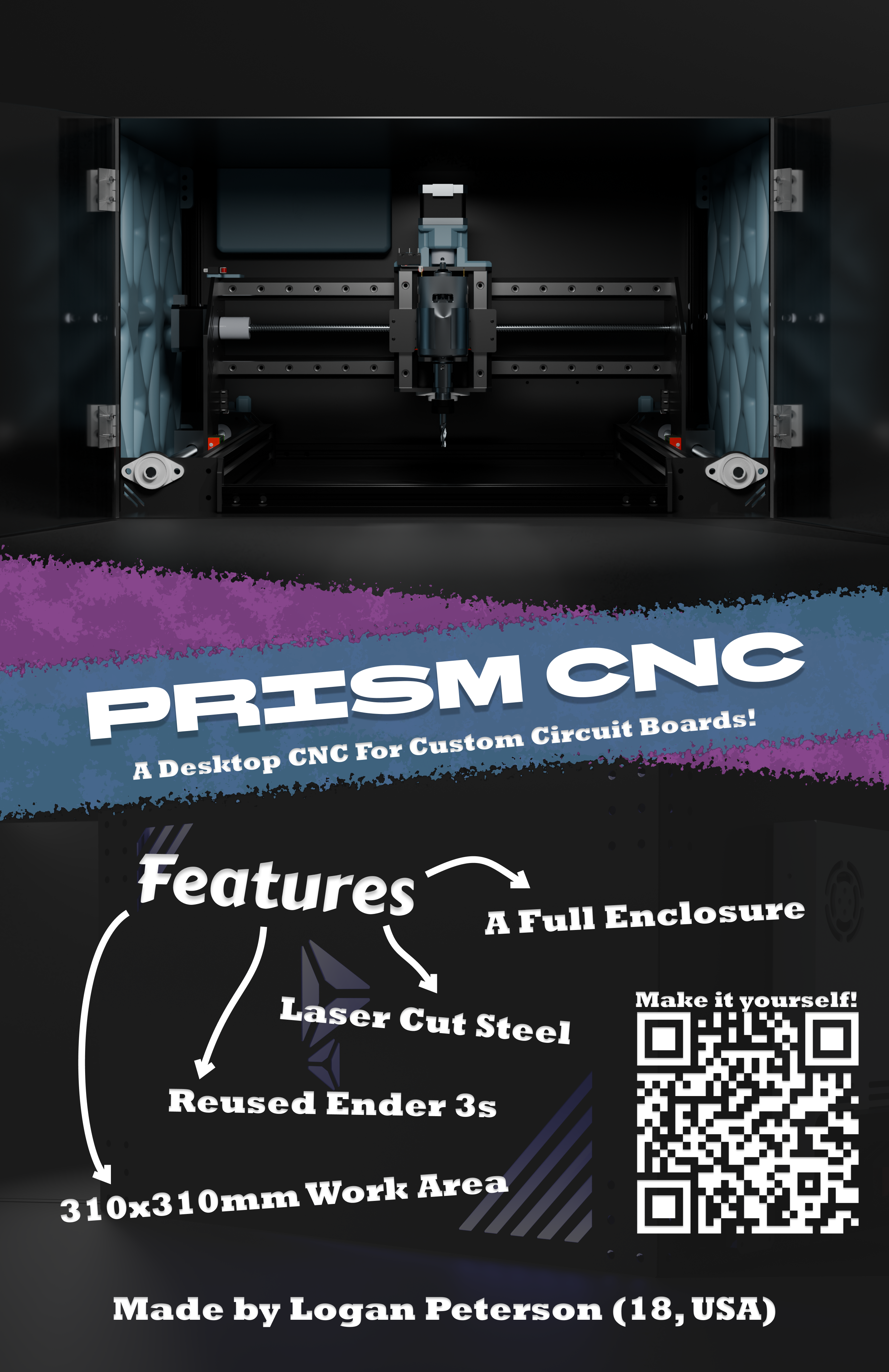
Prism CNC is a compact enclosed desktop CNC router built specifically for PCB milling and small precision work.
The idea was pretty simple:
after getting a 3D printer, I realized how much faster projects move when fabrication tools live in the same building as me.
So this project is meant to bring PCB manufacturing and light milling into that same workflow.
Instead of buying a pile of brand-new motion hardware, I wanted to reuse as much as possible from some broken Ender 3 printers I had lying around. The result is a machine built from a mix of:
- Repurposed Ender 3 components
- 20x20 and 40x40 aluminum extrusion
- Custom sheet metal plates
- Acrylic side panels
- Linear rails
- And a very affordable 775 spindle motor
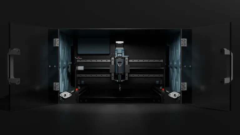
Prism CNC is built to be small enough to live on a desk, rigid enough to do my PCB work, and enclosed enough to keep chips from becoming part of the room decor.
Features
300mm+ Work Area
Because tiny CNCs are sad CNCs.
Using salvaged printer extrusions made the machine dimensions a little weird, but the end result is still a work area slightly larger than 300 x 300 mm, which is plenty for PCB panels and other small parts.
Fully Enclosed Frame
A CNC that throws chips everywhere is just a confetti machine.
Prism CNC uses:
- Sheet metal structural side plates
- Acrylic panels for diffusion and aesthetics
- 3D printed supports
- Front doors for access
This gives the machine a much cleaner look while also helping contain debris.
Ender 3 Hardware Reuse
Broken printers deserve a second career.
A big part of this build is reusing motion and frame hardware from old Ender 3s, which keeps the cost down and gives a pile of abandoned printer parts something more interesting to do.
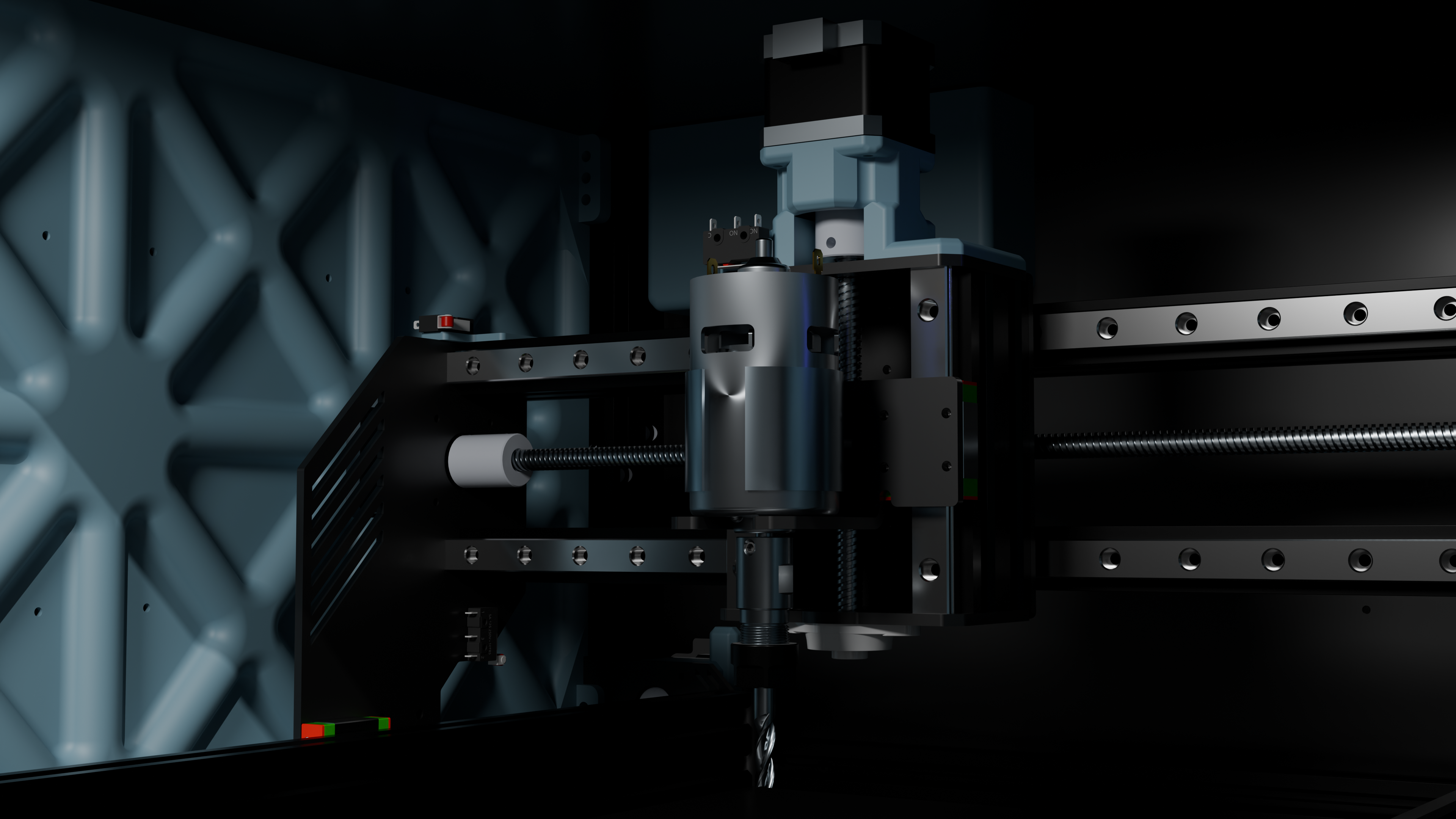
775 Spindle Motor
Definitely not industrial.
Definitely good enough to make it interesting.
The spindle I chose is a 775 DC motor, which works for:
- PCB milling
- Engraving
- Light cutting operations
It’s cheap, easy to replace, and perfectly fine for the kind of small precision work this machine is meant for.
Linear Rails
Because V-wheels were not invited to this project.
The machine uses linear rails for smoother motion and improved rigidity compared to the usual printer-style wheel setups.
Limit Switches
Guessing where home is only works until it doesn’t.
Limit switches were added so the machine can:
- Zero itself properly
- Home repeatably
- Be at least slightly less explosive during setup
Dedicated Electronics Bay
Electronics and flying debris should not be roommates.
The controller electronics live in a rear-mounted compartment, while the power supply is mounted to the rear side wall.
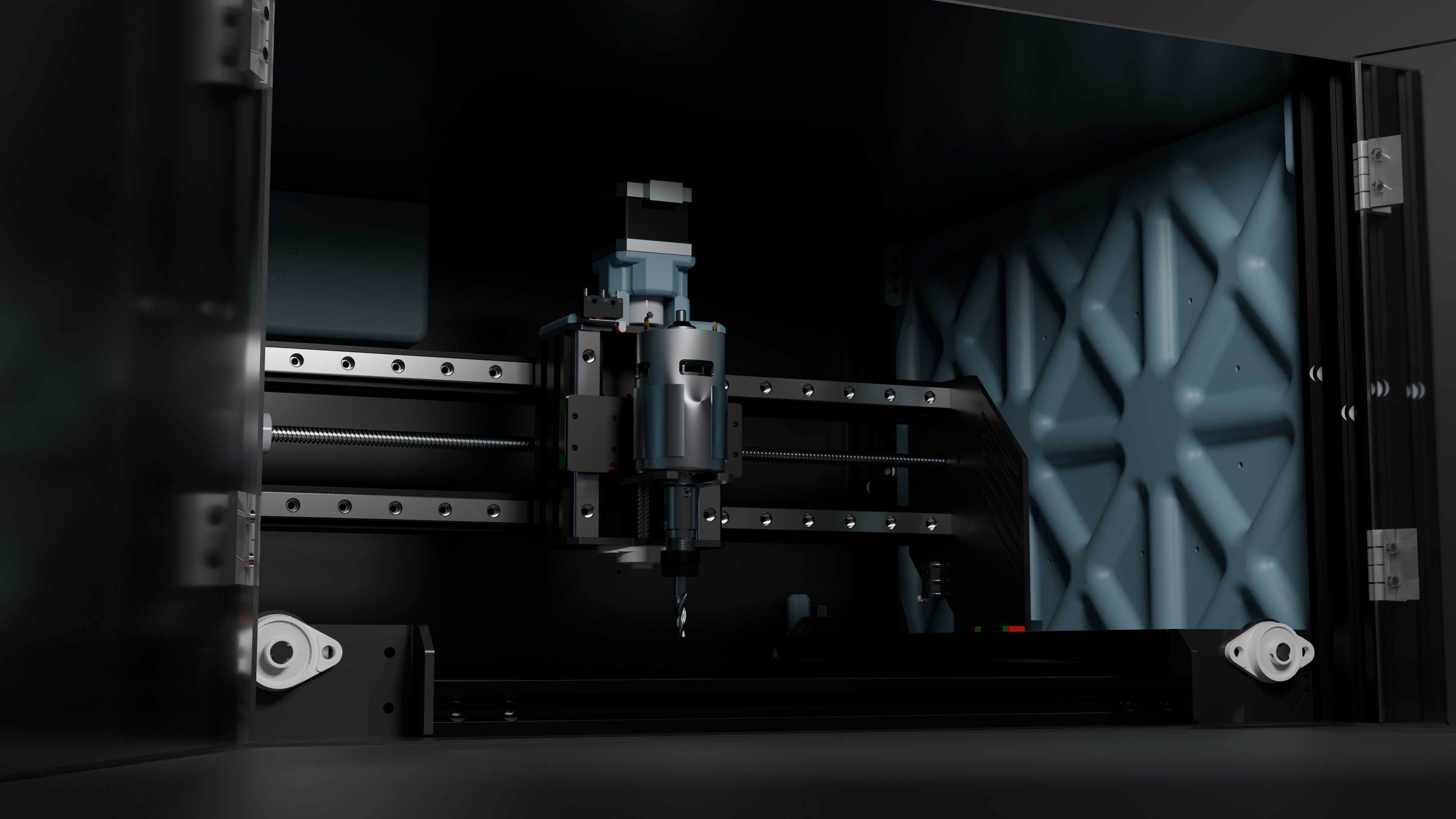
Structure
The main frame is built from both 20x20 and 40x40 aluminum extrusion, tied together with custom sheet metal plates to improve rigidity.
A lot of the structure exists to solve a very specific problem:
how do you turn a pile of salvaged printer parts into something that does not flex like a noodle?
The answer was more sheet metal.
The side walls use a layered construction:
- 3D printed supports
- Thin acrylic panels
- Outer sheet metal walls
This approach keeps the machine compact and rigid while also making it look less like random aluminum extrusions that accidentally became a CNC.
Design Process
This project started with a basic set of goals:
- reuse as many Ender 3 parts as possible
- get a 300mm+ work area
- keep it enclosed
- make it rigid enough for PCB milling
- keep it small enough to actually fit on a desk
From there, the CAD snowballed in the usual way.
The early design work focused on placing the reused ender components. After that came the custom structural plates, motor mounts, enclosure panels, and electronics mounting. At one point the entire machine was being built inside a single Onshape part studio, which was not exactly ideal, so the design eventually got moved into a more proper assembly.
The final step was exporting the CAD into Blender and turning it into renders that actually look cool instead of looking like engineering homework.
Electronics
The electronics setup is pretty simple:
- CNC controller in the rear electronics box
- Motor controller for the spindle
- Power supply mounted on the rear side wall
Why?
Because having fabrication tools at home is insanely useful.
Getting a 3D printer made a huge difference in how quickly I could prototype and iterate on projects. Prism CNC is meant to extend that same idea into:
- PCB manufacturing
- Engraving
- Small precision parts
- General “I do not want to wait for shipping” parts
It fills the gap between designing something and actually holding the finished part.
Or at least it will once I stop staring at CAD and finish making the parts.
Project State
Right now, Prism CNC is in the parts order phase.
The core mechanical structure, enclosure, spindle placement, rails, electronics bay, and limit switch mounting are all modeled, and the current version has proper Blender renders to show where the project is headed.
The next step is turning the nice renders into an actual chip-producing machine.
Future Plans
A CNC project is never really “done,” it just reaches new levels of scope creep.
Planned upgrades include:
- Automatic tool probe
- A better spindle
- Dust extraction
- PCB auto-leveling
Disclaimer
This project is open-source and built wit slightly questionable engineering decisions.
If it:
- flexes unexpectedly
- mills copper into modern art
- launches chips into another zip code
- or develops a personality
that’s on you.